Links
Tags
Christmas in July - Plans for 2022's Christmas Light Show
Oh no! It's only six months until Christmas and there's so much to do! Ok... maybe not for most normal people - but for me, it's time to start ramping up planning to ensure plenty of time for sequencing and a few new props to add to the display.
Pre-buys, ordering and planning
The last few years have not been too kind on part shortages, transport, wars, pandemics - you name it. So much so, that this year if I was to order any lights, they needed to be done early on. In February this year, I pre-ordered a large quantity of LED lights from Light it Up LEDs. Best to order up at the start of the year so you can take advantage of sea-based shipping and any custom requirement you may have from wire gauges, separation between bulbs and connectors available within your string. Lucky for me, there were particular bulbs of interest in stock but if you need them and want to pay the lowest possible amount (which can be quite considerable), it can take several months for them to reach Australia with most in the community only receiving their bulbs in the last couple of weeks.
Secondly, I really needed to consolidate my Raspberry Pi's into one main controller box for the show. While consolidating everything might be a bad idea (one part = bad failure), it'll also help reduce the complexity and the amount of power injection required to light up those long strings. Interestingly, there are new controllers currently under development that will take advantage of the Raspberry Pi's additional GPIO pins called DPIPixels - it'll be interesting to see what form the product takes and how suitable Raspberry Pi Zero's might be at making cheap(ish) controllers. On the other end of the spectrum might well be dedicated controllers over at Experience Lights that made an appearance in the last couple of days. Exciting to see some new functions that will also reduce your build complexity for newcomers to the hobby.
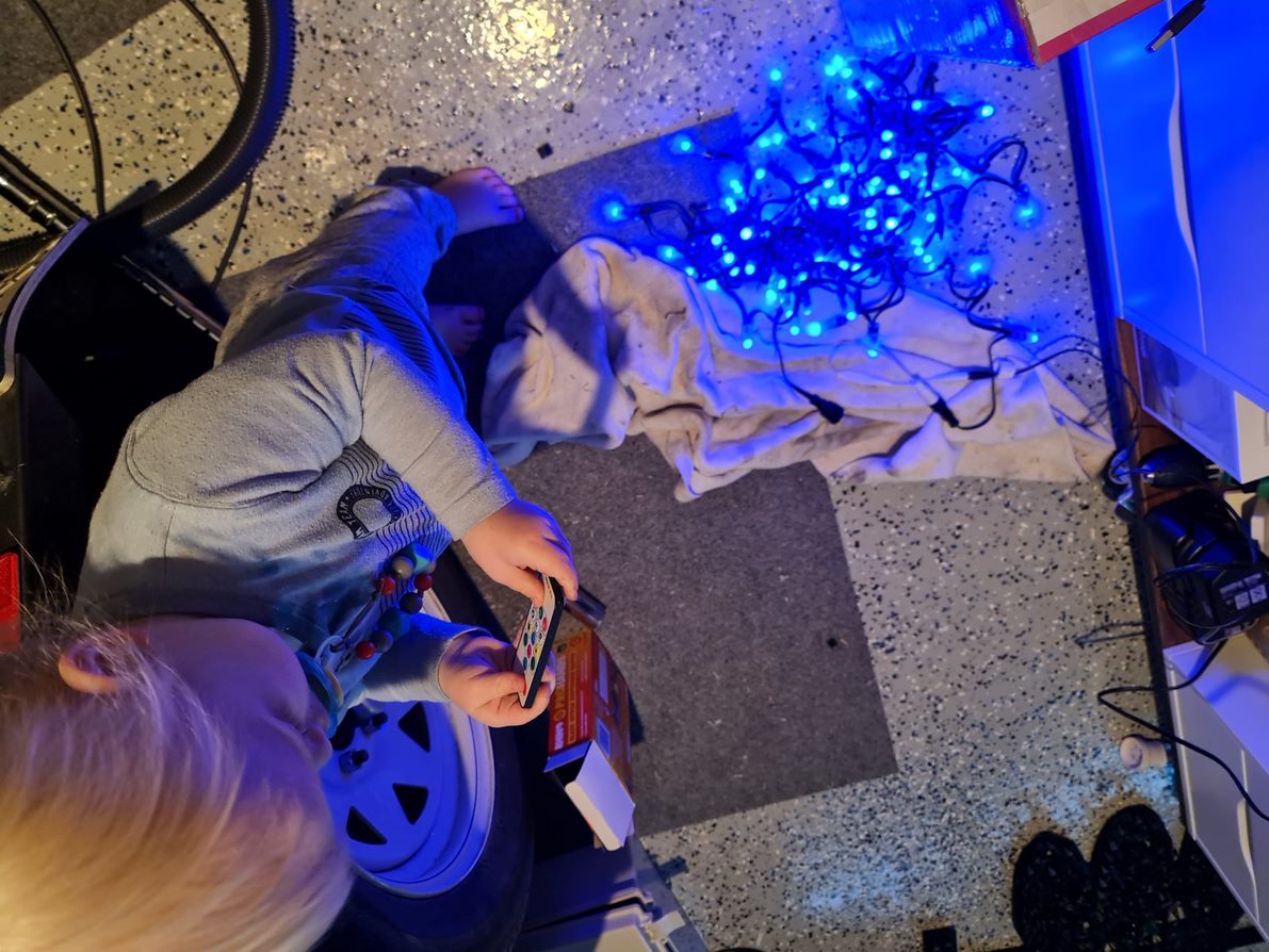
Thirdly, I'll need to crank up the 3D Printer again and procure a number of twin-wall sheets to start cutting out the new additions for this year's show. Thankfully, this year I have a new helper who has started helping by testing the LED bulbs from last year's poorly made matrix.
Assembling the new controller box
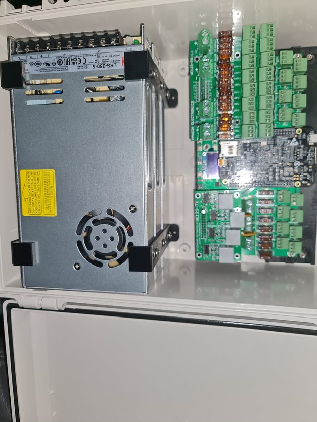
It's not been easy in finding the right components for this one. I figured this year I'd need a large enough box to store 3x 300w Meanwell power supplies in for both 5V and 12V running. This box, whilst having a lot of ports won't have a lot of lights hanging off of it. A few props and the LED strips amount to perhaps 2,500 lights total so as long as there's some separation, I should be able to get some reasonable airflow in there.
To begin, this year's controller of choice is Hanson Electronic's HE123mk2 controller. There are a number of reasons I like this one. (1) I get to put a Beaglebone to good use that I've had lying around for several years and (2) the board layout here ensures that the wiring itself does not cover up the fuses making it easy to spot dead fuses (they light up on failure) and replace them. It's a solid, well priced board with options to expand over your standard Cat5/6 cabling. This will cover any possible future expansion I might have, and the board looks to be very repairable. Given the chip shortage and inflated controller prices, these really do represent good value.
With components acquired and my previous box decimated for the power supplies, I got to work on 3D Printing a suitable apparatus for stacking Power Supplies. I only have a 200mm x 200mm 3D Printing Plate and this box is some 225mm wide. Naturally, you can print a plate around about 70mm x 225mm if you angle it 45 degrees, but then you need to watch for crazy 3D Print head movements to cater for your new angle. These won't be seen, so as long as I can print some platforms, I'll be able to screw things into place.
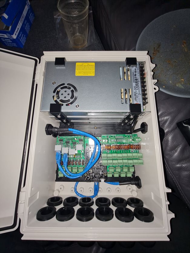
Now for a Pro Tip - I was able to source 4 hole cable glands on eBay from a Solar installer - these really do help reduce the swiss-cheese nature of the build but also provide a good way on managing the cables you need to pass through. You can also buy from Hanson Electronics (and this link is likely to continue working long after the eBay one expires) if white is your colour.
Pro Tip: When installing these, crimp your bootlace ferrules first, then thread the cable through the cap and rubber seal second, then push through the hole third before screwing into the terminal. If you don't, you won't get the cable through. At least my experience above is the rubber seal does not have a cutout to thread things through, and given the thickness of the LED connections, it's unlikely you'll get more than one through the cap.
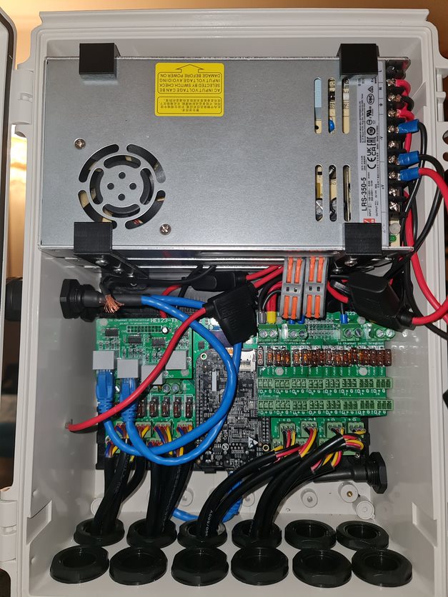
I'm no sparky which is why I don't do a detailed walkthrough of building a box, but it's a necessary evil in this hobby to be able to wire things up. After all, you can nearly guarantee you'll be replacing a bulb or two during the show - so you might as well get used to it now. In hindsight, I probably could have gone up a box size to help with airflow (still need to install fans on the cover to help push air through and work out how to get a temperature sensor working on the Beaglebone).
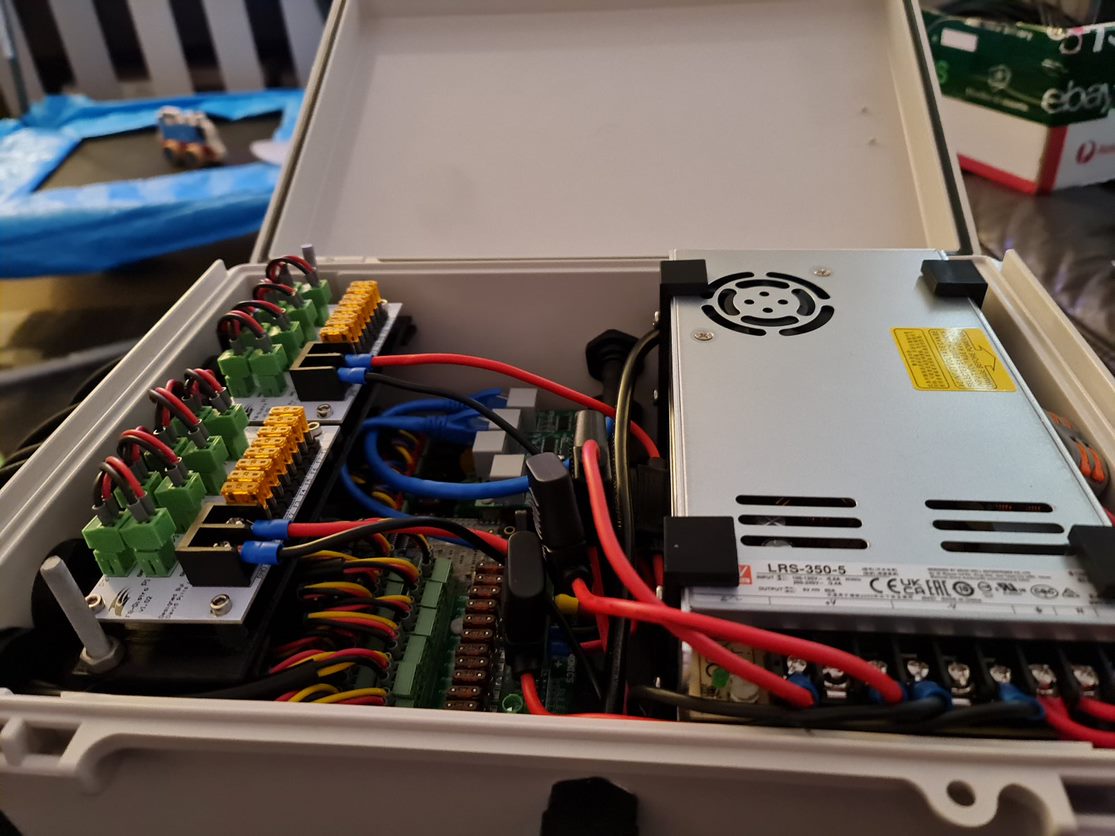
And that's it. unfortunately it's a little bit of a mess given the fuses all over the place but I do have 48 cables going out the bottom and room to mount a couple of fans to help with airflow. Overall I am quite happy with how this one came out - I managed to get the measurements right and holes lined up better than this time last year.
Anyway - that's enough Christmas talk for July. I've put up a resources page that I'll populate over the coming months with some STLs for this box and some sequences I used last year that are more unique than they were heavy inspirations of. You can check that out over here.
Knobs, Wiring and Buttons - Progressing on the A320 FCU
I haven't had a lot of time the last few weeks to work on the FCU much further, however there are a couple of updates worth sharing.
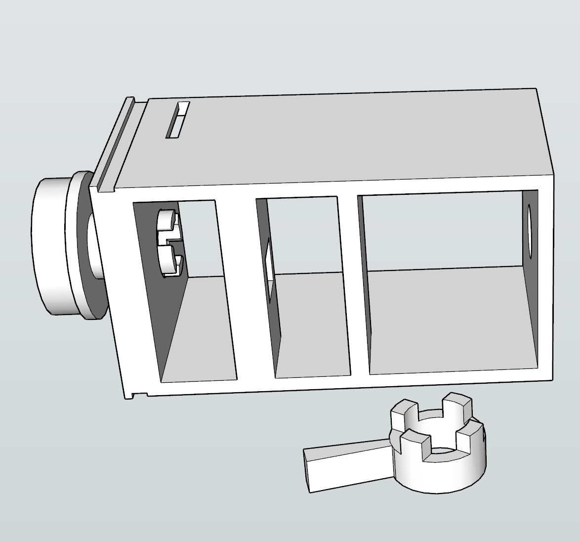
Minor redesign to the back plate
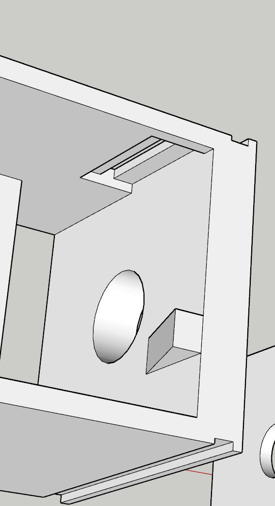
I had this grand idea to make insertable Korry's into place and have them as removable independent units. Unfortunately, those LED lights wouldn't fit inside the chamber I had printed and the outcome wasn't great. To get around the need to glue and design all of those components, I had completed another design - this time where the chamber was integrated to the backplate. As I wasn't too sure about the tolerances here, I had printed a few different sizes to work with the Korry inserts but I really only had one shot at getting the backplate done.
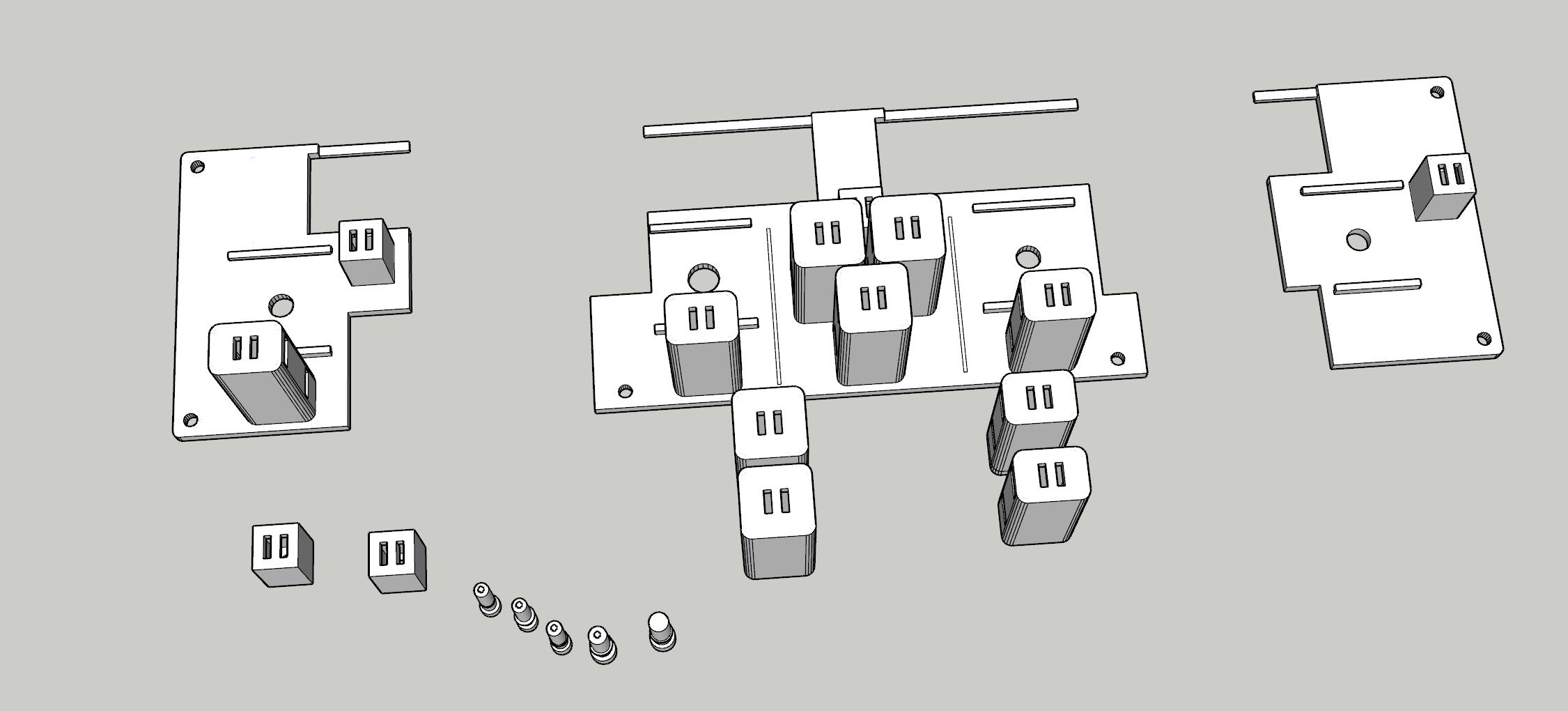
With this out of the way, the next step was to insert buttons and led lights into each of these new chambers. Again, this took several goes that I had pre-empted and thus the creation of different sizes - but thankfully things like leaving a large gap to slip the buttons in really helped out here. It was fiddly though, and you really get to know just how tight (i.e. < 0.1mm inaccuracies) things may fit or require a bit of filing and cutting to get things in snug.
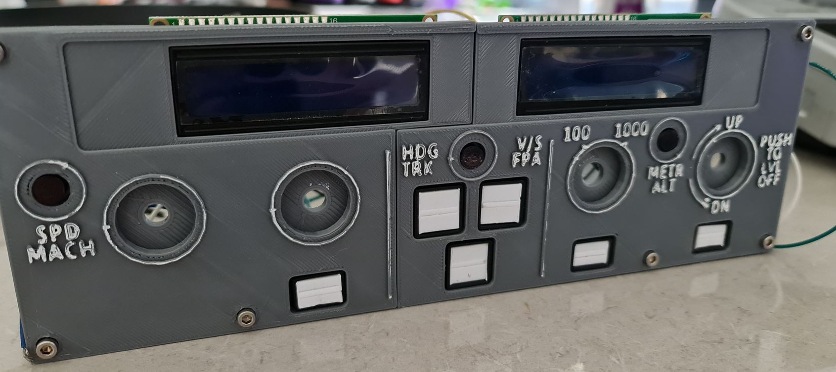
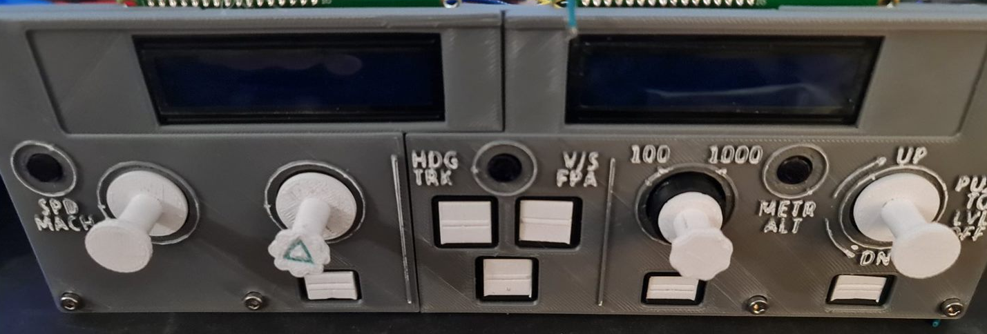
With the screens in place, it's starting to come along.
Installing the Rotary Encoders
I've spent a bit of time going back and forth on getting a good, repeatable push-pull rotary encoder working and in the middle of doing this had learned a few more quirks about the printer - especially printing such small volume items. For the Rotary Encoders in particular, when I began I was printing shells, stalks and knobs altogether with the same material. As I started printing smaller volumes, I started getting stringy mess and prints that wouldn't be loose enough around the rotary encoder itself.
Having not had to level this printer for a few months, I figured at the very least I'd clean up the bed, re-level it manually and give the internals a good clean too (ensure the filament isn't slipping in the extruder from a build-up of gunk). I'd 3D Print a calibration cube and everything was within known tolerances (< 0.1mm on the Z axis but otherwise everything else recorded a perfect 2mm). I had printed a few other things at the same time and they also come out well without stringing. It finally dawned on me that perhaps the part was 'too hot' and wasn't given enough time to 'cool down' before applying the next layer. So to remedy the next print, instead of printing one stalk - I printed all the working parts and things kind of went back to normal.
The reality is that when you start playing with your printer - you start having to 'learn' all the quirks again. Having a more level bed and now knowing about volume of prints to help dissipate heat means you're back to calibrating your software settings to compensate too. So it's fair to say that it took quite a few goes before usable prints were coming out.
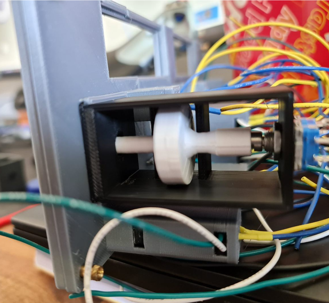
With the first prototype in place things are looking on the up. This particular switch has the right clearance off the button at the back and works perfectly. I perhaps had unrealistic expectations that the same will occur for the other ones - but unfortunately it didn't quite work that way. For the second rotary encoder, the disc didn't quite go all the way down on the rotary encoder so the disc itself in the 'release' mode was touching right up against the pull mechanism - not a great outcome. It's fair to say that in hindsight, I would probably use a longer stalk button to remove that margin of error and perhaps had a bit more of a gap and maybe a spring to help. In any case, something to improve on.
Things get a bit more challenging for the altitude selector. There's an outer ring that selects either increments of 100 or 1,000 - this would need to sit around the stalk and be some kind of a compression fit to hold the selection. I don't expect this mechanism to last long - and perhaps a second encoder or toggle switch might have helped (there are plenty of options on Thingiverse). Behind the scenes would be a microswitch that by using very little friction at all, can sit on the microswitch when activated.
With the selector and activator connected together, and the microswitch installed - we should be able to select 100 or 1,000 with some creative license by rotating the ring. The final piece of the puzzle was working out how far the grip should protrude. Apart from having to print this a few times, this was perhaps the easiest part to assemble and now the knob and selector fit reasonably well.
What's next?
I'm at the final stages now of the assembly itself leaving behind some fiddly and trivial components.
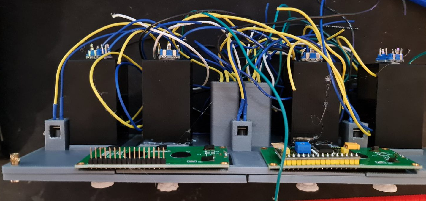
- An Arduino Mega 2560 needs to be wired up. I've got some proto boards ready to solder all the wires to.
- A shell for the components to sit in. This is currently printing whilst typing.
- Printing some Korry labels - this will likely be a transparency on a white sheet of paper.
- Get this all running and working in Flight Simulator, via SimConnect.
- Final decorations - black shroud for the LCD screens for example.
It's fair to say that should this be a repeatable design, I think I would embrace sacrificing imitation for simplicity. For example, the Korry 'pull' action might very well be replaced with additional push buttons on the face. That would then leave the rotary encoders available for a very simple installation. The same applies for the 100/1,000 selector - that might well be a toggle button or a switch. The Korry switches themselves could be made significantly smaller with a larger button - possibly a Cherry MX style key switch. The 1602 LED screens might well stay, although a future version I want to wire up using custom 7-segment displays and LED status lights. None-the-less, it's been a great learning project and hopefully we're only one or two posts away from testing a flight from Melbourne to Sydney.